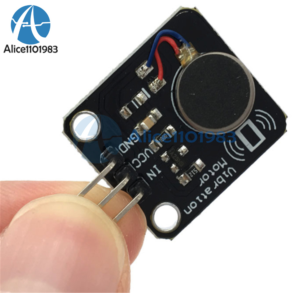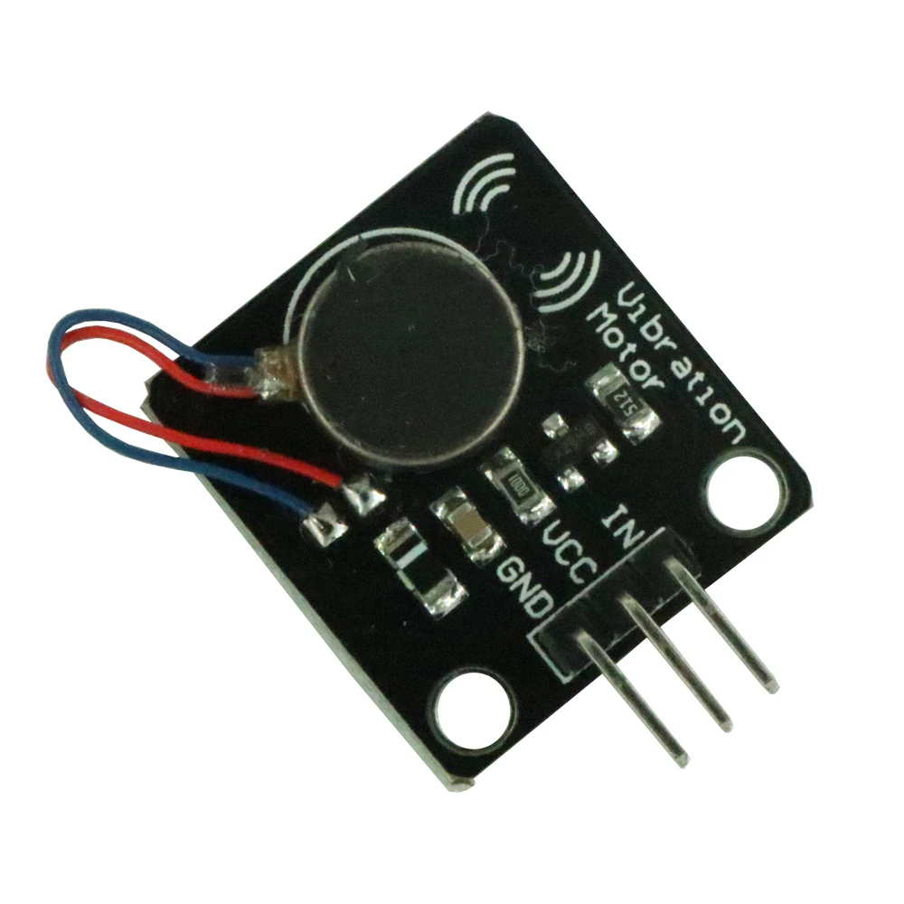
If extra security is required, consider the moulding securing walls within the enclosure body. Also, higher frequency harmonics are absorbed and reduced by the rubber ‘boots’ that enclose these kinds of motors. This makes assembly easier for applications where it’s desired to have the motor mounted to the enclosure.

Spring PCB vibrator motors have spring-loaded fingers on the motor which mat with pads on the PCB. It is recommended that this mating surface is clean, dry, and offers a good unified fit to the motor backing-plate (on which the self-adhesive pad is stuck). The acrylic adhesive is considered to be resistant to most solvents, UV light, moisture and temperature extremes.Īs with all adhesives, the final bond strength is dependent on the cleanliness of the mating surface. These 0.16mm thick adhesive tapes typically offer a 180 deg peeling strength of 15N/20mm, and a tensile strength of around 20N/10mm. Three brands of adhesive are typically used on our coin vibrator motors depending on availability (they all have very similar specifications). The adhesive allows for a secure mounting of the vibration motor to a wide range of surfaces such as PCBs or flat internal surfaces of the enclosure and makes manufacturing installation fast and clean. They come with either spring PCB connectors or a high-strength long life self-adhesive backing sheet that is pre-attached to the underside of the chassis. The disc rotates and, due to the built-in off-centred eccentric mass, the motor vibrates!Ĭoin vibration motors are designed to be easy to mount. The commutation circuit alternates the direction of the field through the voice coils, and this interacts with the N-S pole pairs that are built into the neodymium magnet. This field interacts with the flux generated by a disc magnet that is attached to the motor chassis.

Two brushes on the underside of the plastic disc make contact to the PCB commutation pads and provide power to the voice coils which generate a magnetic field. The vibration motor rotor consists of two ‘voice coils’ and a small mass that is integrated into a flat plastic disc with a bearing in the middle, which sits on a shaft.

They have the same motor drive principles, including H-bridge circuitry for active braking.īrushed coin vibration motors are constructed from a flat PCB on which the 3-pole commutation circuit is laid out around an internal shaft in the centre. Therefore they can be driven in the same manner as their pager motor counterparts. Our coin or pancake vibrating motors are all Eccentric Rotating Mass (ERM) motors.


 0 kommentar(er)
